


No products in the cart.

Phil and Ginni Lyons
January 30, 2026
41 views
Why Your LiFePO4 Batteries Cut Out at Sunrise. The 29-Volt Surprise.
I'm setting up my charge controllers for the solar and battery bank. My batteries have a recommended charge current of 40 amps. The maximum is 50 amps. Since I have dual charge controllers, should I set them to 20-25 amps? Or 40-50 amps? It makes sense to cut the amps in half. But then I considered the bank being series/parallel, which might allow for a greater charge current. Any help is appreciated. Post by: epretot
Post by: freds
Do you have enough solar panels to exceed this charge limit? Do both solar arrays output in sync, or does one produce more power in the morning and the other in the afternoon? If you have Victron equipment, you can use a GX control computer to implement DVCC (distributed voltage charge control). This would automatically balance between the two charge controllers to provide the maximum charge output.
But it sounds like you already have your charge controllers, so yes, set them both to 20 Amps. You may have less than full production.
Post by: epretot
I do have two Victron blue solar controllers. I quickly realized I should have purchased smart controllers. Are the blue solar controllers compatible with the GX? The big disappointment in my setup is that my controllers don't synchronize their charging. To answer your question. I don't have enough data to definitively determine whether the panels' outputs differ. I just turned them on yesterday. However, I'm getting 65-66 Volts from each array as it stands.
I also haven't really depleted my batteries much. I'm in testing at this point, so I'm going to leave the shore power off for a while.
Post by: epretot
In summary, here is all my information:
- I have two arrays, three 200W panels each.
- 24V battery bank (see charging specs above)
- Two charge controllers 100/50 MPPT
Post by: freds
Yes, they do interface with the Venus OS GX devices. You also need a USB adapter cable. Your options are:
1. Color Computer CCGX (old but works, going to sell mine soon).
2. CERBO GX, which is the current device, but it needs an external screen. There are lots of interface options.
3. Raspberry Pi 4 with Venus OS image (which I am transitioning to).
The last two options allow you to run a large OS image that integrates Node-Red into the environment. With any of these options, you get access to the Victron VRM cloud and use a phone app. Read through my 1980 Prevost build thread for more info.
What BMS are you using with your batteries?
Here is some more reading:
https://www.victronenergy.com/media/pg/CCGX/en/dvcc---distributed-voltage-and-current-control.html
https://community.victronenergy.com/questions/160294/clarifying-dvcc.html
Post by: freds
24V times 40A equates to a 960W of maximum charging rate. You have 1200 watts of panels. Your solar controllers can handle up to 2400 watts of solar panels. I assume they are flat-mounted, so at the most, you might get around 1000 watts, and generally, as the sun moves, more like 800-900 watts.
Unless you are interested in automation and reporting, just set each controller to 25A, and there is little chance you will damage anything.
Post by: freds
There are a couple of YouTube channels you might like to watch:
This channel deals mostly with the Cerberus GX:
https://www.youtube.com/@OffGridGarageAustralia
This channel deals mostly with Raspberry Pi 4 with Venus OS:
https://www.youtube.com/@tobisreallifeskillswithtobi
Post by: epretot
I really appreciate the help. I'm learning a lot. I just want to stay out of trouble for now. Learning to make the system more efficient is a future goal.
I'm using SOK batteries with a capacity of 206Ah. They have an internal BMS. What are your thoughts on that?
Post by: freds
I think you will have to use the Victron Smart Shunt as the source of truth when using DVCC mode. It needs a Direct USB adapter:
https://www.amazon.com/Victron-Energy-VE-Direct-USB-Cable/dp/B01LZ6WTLW/ just as the smart solar controllers need.
In my case, I use a USB hub to connect these cables to, and then a single USB cable to my CCGX device.
Post by: epretot
I had a little glitch in the system the other day. I looked at trends stored by the BMV and discovered this (see image).
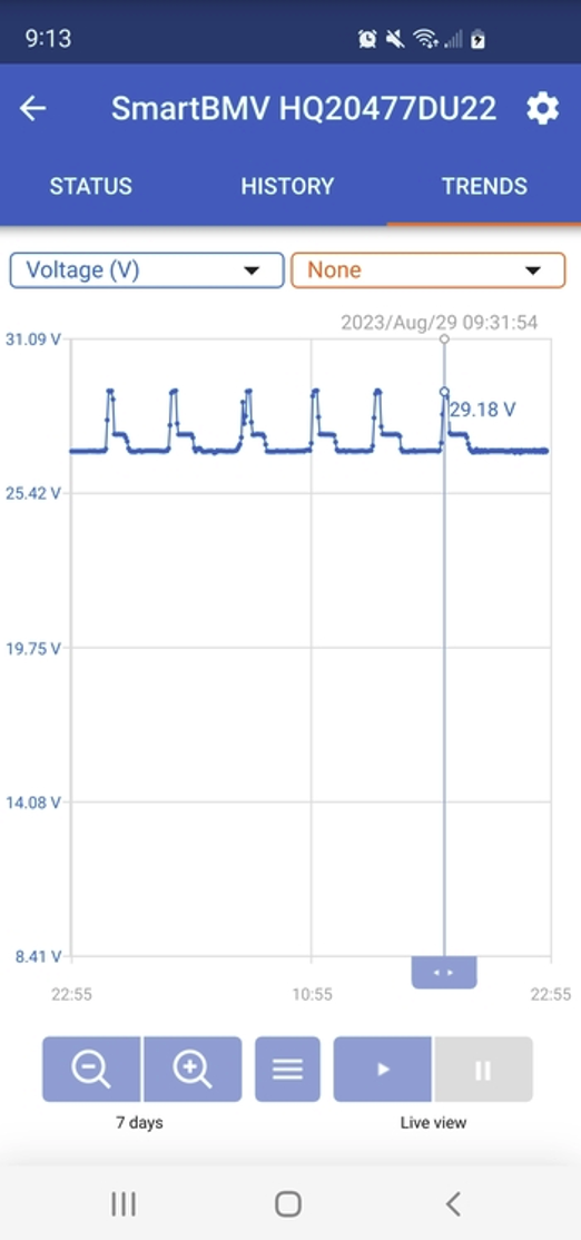
The battery voltage must have exceeded the maximum voltage shutdown of the battery bank, resulting in a loss of power. I'm still learning, so I'm not sure where to go from here.
The graph shows the same spike every day. About the time the sun starts hitting the panels. I turned off the panel breakers, and lo and behold, no voltage jump. There is an exception. I got a similar jump one late afternoon.
Is this a problem? And should the controllers be managing this? The charge voltage is set to 25A.
Post by: windtrader
I did not chime in earlier because I'm more in line with epretot regarding configuring Victron equipment. I swapped in a 24/3000 multiplus inverter/charger, a SmartSolar charge controller, and a Cerbo GX.
I have noticed a similar spike, but have not studied to understand its origin. It could be the charge controller switching off for a moment, but that would drive the open circuit voltage, which would not pass through the system. This can be eliminated by monitoring for the spike once the battery is full, in the evening. The other possibility is that the inverter/charger might perform an operation, but it couldn't generate a voltage higher than the battery voltage.
If the solar controller is switched off due to full charge, again, it can't pass higher voltage down the line. However, when connected to the GX via the Ve Direct cable, it can and does send status, so it could send open voltage.
I think I need one more Victron component, but I’m still assessing whether I do. The Multiplus is connected to the GX via Ve Direct and the SOC, as those parameters are set in the inverter for calculations.
I was thinking that SOC may not be accurate because there is a DC-DC buck converter (Editor’s Note: A buck converter is a step-down converter) that does not pass energy through the inverter, so the SOC would miss this discharge from the DC-DC device and be inaccurate.
Then I thought the inverter could calculate SOC using voltage, but that is faulty thinking. At present, I have not pressed the buy button for a SmartShunt placed directly on the battery terminal line to ensure that all drain from anywhere is captured and reported to the system, thus ensuring an accurate SOC value.
Post by: thomasinnv
The voltage spike and subsequent DC disconnect are due to the BMS high voltage cutoff. If you are charging at 29.2V, that is most likely the BMS's high-voltage protection limit. With LifePo4, charging to 3.65V per cell is not necessary and is actually advised against.
For a 24V system, I would set the absorption voltage to 28.4 - 28.6V, float at 27.4 - 27.6V. Shunt settings should be set to 0.1 to 0.2 volts below the absorption setting, with a tail current of 2% to 3%, a Peukert exponent of 1.01, a charge efficiency of 99%, and a charge detection time of 3 min.
If you are using two 12V batteries in series, you need a balancer between them. Contrary to what many people believe, LiPo4 batteries WILL become unbalanced in series strings, especially if they reach the high-voltage cutoff.
Post by: windtrader
I see the same thing and have no Victron BMS. I do have a Victron charge controller that might cause this, too. I will report back after studying it a bit more. I need to adjust 28.0V on a charge cutoff (3.5 x 8), maybe even less. It does settle down once it cuts the solar to about 26.5-27 volts and stays there for the duration (3.3 x 8)
Do you have a GX device? I haven't had time to dig into the logging and reporting. I'd bet the answer is there about what was going on during those spikes.
Post by: epretot
I do not have a GX.
Post by: epretot
| Quote from: thomasinnv The voltage spike and subsequent DC disconnect are due to the BMS high voltage cutoff. If you are charging to 29.2V, that is most likely the BMS's high-voltage protection limit. |
This was in fact the case. I changed multiple settings after reading your reply and some additional research. With that said, I set the Absorption to 28.8V. The minimum recommended Absorption by SOK suggests 14.4V (x2). However, I am still getting a glitch every morning. No complete power failure, but glitches.
Post by: thomasinnv
Most likely, the cells are not balanced. I would set the absorption and float voltages both to 28.4 for a few days. Holding the batteries at a higher float voltage for a few days will give the internal balancer an opportunity to do its job. Most likely, the BMSs have passive balancers that operate at fairly low current and usually only work near the absorption level.
Edit to add: I just went back and reread your original post. You say you are running 12V batteries in series/parallel. You really need to have a balancer between the series-connected batteries. Unlike lead-acid batteries, LiPo4 batteries can and will become unbalanced when in series. Victron makes a nice little 1-amp automatic balancer just for this purpose.
https://www.victronenergy.com/batteries/battery-balancer
Post by: epretot
I'm not certain I understand what causes the jump. Or a better way of saying it is: “I don't understand why the jump is an effect of unbalanced cells.” I should also mention that the glitch is on the AC side and always corresponds to the spike. Specifically, right at the start. Then everything normalizes despite the increased voltage for two or three hours. The giveaway is that the dehumidifier quits, and the oven chimes when the clock powers back on. But once powered back on, they behave normally.
Post by: thomasinnv
The jump in voltage is usually caused by the BMS momentarily disconnecting the battery, typically due to either a high bank voltage or a cell imbalance. If cells are not balanced, a cell can reach the high-cell-voltage protection cutoff limit (usually 3.65 volts) before the overall pack high-voltage limit is reached. For example, if cell #1 (it can be any cell, I just picked #1 as an example) reaches 3.65V but the remaining cells are all 3.60V, the overall pack voltage for a 12V battery is going to be 14.45V which is below the pack over voltage protection of 14.6V, but the BMS will disconnect because of the single cell protection limit of 3.65V.
In your case, you are connecting two 12V batteries in series to achieve a 24V nominal bank. In this case, you could have either a cell imbalance or a series imbalance. Say you have a voltage difference of 0.2V between the upper and lower batteries in the series connection. The maximum allowed voltage for the series-connected batteries is 29.2V, with a 0.2V difference between the batteries.
Once you reach 29V, you will actually have one battery at 14.4V and the other at 14.6V. Then the 14.6V battery disconnects because of the overvoltage protection. Over time, series-connected LiPo4 batteries WILL become unbalanced, especially if they are charged at or near the maximum charge voltage.
Post by: epretot
Follow-up question...why is this causing a problem when on shore power as well? This makes sense if the system was inverting, but not on shore power. Even on shore power, I see the effect. Again, the time stamp on the graph always matches the time of the glitch.
Also, is this image the correct installation of the balancer? It seems as though multiple balancers would need to be installed between each series.
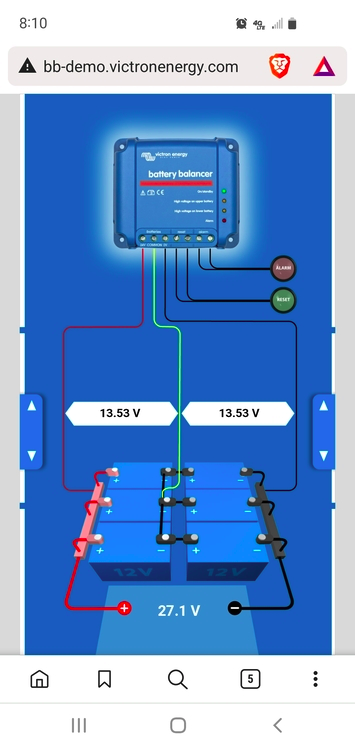
The battery balancer will be delivered today. I'll install it this week.
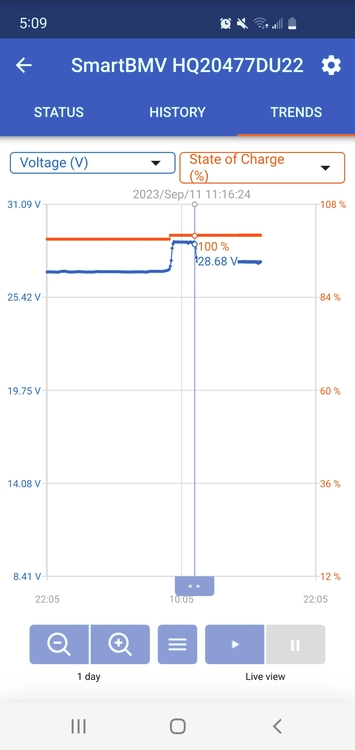
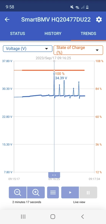
This is a snapshot of what occurred this morning. This is the highest voltage jump yet. Complete power loss on the AC side with no interruption on the DC side. I don't understand that.
This is the 3rd day of having the absorption voltage and float voltage set to the same voltage (28.8V)
Post by: thomasinnv
You still appear to be experiencing high-voltage disconnects. As I said before, you most likely have an imbalance between the series-connected batteries. To use a single balancer with series/parallel batteries, you have two options.
1. You will need to connect the batteries into two parallel groups and then have a single series connection. 2. You can retain multiple series strings, but you will need to connect all the midpoints together. The manual for the balancer will have a diagram.
BUT WAIT... THERE'S MORE!!!
Click on the link below to read additional comments that were added after we published this post. There are many more comments with even more information that may be useful to you and your bus.
Forum content extracted by Phil Lyons, our Chief Forum Moderator. To read the rest of this discussion in the Forum, click this link:
https://www.busconversionmagazine.com/forum/index.php?topic=36813.0
Discussions like this take place on a daily basis in the BCM Online Discussion Forum.
To read them go to:
https://www.busconversionmagazine.com/forum/index.php
Anyone can read the discussion board, but to get the most out of the Forum you need to join by clicking the “register” link above the login box in the upper left section of the Forum page.
Registration is free and once registered you will be able to view all the available discussion boards, view images, lookup and contact other members, reply to other members, share your own experiences for others to learn from, and most importantly, post your own questions.
See you on the Forum!
Article written by Phil and Ginni Lyons
Phil Lyons has been a Bus Nut and moderator of the BCM forum for many years. He and his wife Ginni live in the central highlands of Arizona. Phil’s day job is in IT Security and Ginni is a retired Registered Nurse.
They are the proud parents and grandparents of daughters, granddaughters, and two spoiled dogs.
Phil and Ginni are part of a bluegrass/gospel trio called Copper Mountain String Along, are members of Bethel Baptist Church in Prescott Valley, and volunteer and serve in various capacities in the church and the community.
RVing has been part of their lives for over 35 years, and they both hope to enjoy the bus lifestyle for many more years.
You can contact Phil via email at
Phil@BusConversionMagazine.com
To be the first to read all new articles and to read thousands of articles about conversions back to 1992, become a member of BCM.
Click HERE to become a Member now!Click on any image in this column
to open the company's website.
to open the company's website.
